
In the high-stakes environment of major steel construction, a discrepancy of mere millimeters in material thickness can cascade into catastrophic structural compromise, multi-million dollar rework, and protracted contractual disputes. For Project Managers, QA/QC Engineers, and NDT Inspectors operating under Engineering, Procurement, and Construction (EPC) frameworks, the challenge is stark: contract documents mandate compliance with stringent standards, but the path to achieving defensible, accurate measurements on a dynamic job site is often unclear. This gap between theoretical requirement and practical execution represents a significant project risk.
This definitive guide bridges that critical gap. We move beyond generic technical overviews to provide a comprehensive, actionable framework for implementing thickness measurement protocols within the rigid compliance structures of EPC projects. You will find not just the “what” of standards like ASTM and ISO, but the “how” of integrating them into Inspection and Test Plans (ITPs), executing field procedures that withstand audit, and creating documentation that mitigates contractual and safety liabilities. Our goal is to transform thickness measurement from a potential point of failure into a demonstrable pillar of project quality, structural integrity, and financial control.
- EPC Standards & Thickness Measurement: The Foundational Link
- Technical Guide: Using Ultrasonic Thickness Gauges on Steel
- QA/QC Integration: Compliance, ITPs, and Project Documentation
- Advanced Topics: Calibration, Technology, and Special Cases
- Conclusion
- References & Cited Standards
EPC Standards & Thickness Measurement: The Foundational Link
In the EPC project delivery model, the contractor bears single-point responsibility for engineering, procurement, and construction, making integrated quality assurance a contractual imperative, not an optional add-on. Thickness measurement standards within EPC contracts are typically not standalone rules but are integrated by reference to established, authoritative industry codes and standards. Precise control of material thickness is non-negotiable from a business and operational perspective, directly impacting structural calculations, corrosion allowance, fitness-for-service assessments, lifecycle costs, and ultimately, the safety and licensability of the asset.
The U.S. Department of Energy’s guidance for major projects explicitly states that when using EPC contractors, contracts must “fully describe the expectations for Quality Assurance activities,” ensuring these requirements are woven into the project lifecycle from design through construction [1]. This creates a clear, enforceable chain of requirements. Furthermore, research from the Construction Industry Institute (CII) validates that measuring quality—including dimensional verification like thickness—must be a process “integrated into normal execution procedures” to positively influence project outcomes [2]. Therefore, within an EPC framework, thickness measurement is a critical quality performance indicator with direct links to contractual compliance and risk management.
The Role of Referenced Standards: ASTM, ISO, and AISC
The technical backbone of any EPC thickness requirement is a set of referenced, universally accepted standards. These provide the legally defensible methodology that ensures measurements are accurate, repeatable, and auditable.
- ASTM E797 / E797M: The primary American standard for the “Manual Ultrasonic Pulse-Echo Contact Method.” It defines the practice, equipment, calibration, and reporting requirements for ultrasonic thickness gauging.
- ISO 16809:2017: The international counterpart, which specifies principles for ultrasonic thickness measurement and crucially mandates that testing “is performed by qualified and capable personnel,” ideally qualified in accordance with ISO 9712 or equivalent national schemes [3].
- AISC Specifications: The American Institute of Steel Construction provides the governing tolerances for structural steel members. While not a measurement standard per se, AISC specifications define the acceptable thickness ranges and fabrication tolerances (e.g., ±1mm for plates up to 20mm thick) that field measurements are verified against.
These standards are invoked in contract documents, typically within technical specification appendices or quality assurance clauses. For a clear view of how these standards interlock in formal project specifications, the AISC Specifications with ASTM Standards for Steel Construction provides an authoritative reference.
Core Requirements: Calibration, Personnel, and Documentation
EPC frameworks universally mandate three interdependent pillars for a credible thickness measurement program, each acting as a critical control point:
- Instrument Calibration with Traceability: Every ultrasonic thickness gauge must have a valid calibration certificate from an accredited laboratory, with unbroken traceability to national standards (e.g., NIST). Formal calibration is typically required every 6 to 12 months. The certificate must document the reference standards used, environmental conditions (e.g., 20°C ±2°C), and stated measurement uncertainty.
- Personnel Qualification: Following ISO 16809’s lead, technicians performing measurements and evaluating results should be formally qualified. In practice, this is most commonly certification to ASNT SNT-TC-1A or ISO 9712, typically at Level II for independent work. Their certification records are as vital as the instrument’s calibration certificate for audit purposes.
- Documentation Protocols: Every measurement must create an auditable trail. Required documentation includes: the specific calibrated gauge used (serial number), the qualified technician, exact measurement points (referenced to drawings or GPS coordinates), raw readings, environmental conditions, and the final evaluated thickness against acceptance criteria. This trail is the primary evidence for compliance.
Technical Guide: Using Ultrasonic Thickness Gauges on Steel
Translating referenced standards into reliable field data requires a disciplined, step-by-step approach. The ultrasonic thickness gauge, operating on the pulse-echo principle (measuring the time-of-flight of sound waves), is the industry workhorse. Key technical parameters for steel include a sound velocity of approximately 5920 m/s, a typical measurement range from 0.08mm to 635mm, and a standard accuracy of ±0.1mm or ±0.1% of reading [4]. The foundational methodology is codified in standards like ASTM E797, but successful field application depends on rigorous procedure.
Pre-Measurement Protocol: Calibration Verification & Surface Prep
Before any project data is recorded, two non-negotiable checks must be completed to ensure data integrity:
- On-Site Calibration Verification: Prior to each use or shift, verify the gauge’s accuracy using certified reference blocks spanning the expected measurement range. This daily check confirms the gauge is functioning correctly for the specific task and is distinct from the annual formal calibration. Document this verification.
- Surface Preparation: The measurement surface must be clean, bare metal. Remove all loose scale, rust, paint, and coatings to ensure proper ultrasonic coupling. Industry data indicates that surface roughness exceeding 6.3μm can introduce measurement errors of up to 0.5mm [4]. Proper preparation is a direct requirement of ASTM E797 and is critical for obtaining a clear, reliable ultrasonic signal.
For a detailed, authoritative example of a field procedure that incorporates these critical steps, consult the LANL Engineering Standards for Ultrasonic Thickness Examination.
Measurement Execution: Technique, Pitfalls, and Best Practices
Even with perfect preparation, operator technique is the final determinant of accuracy. Common pitfalls directly lead to the “inaccurate thickness measurement” issues that plague projects.
- Coupling & Alignment: Apply a thin, consistent layer of ultrasonic couplant. Hold the probe perpendicular (90°) to the surface. Angling the probe lengthens the sound path, causing a falsely high reading. Inconsistent pressure can also vary readings.
- Multiple Readings & Location Selection: Take a minimum of 3-5 readings at each designated measurement point to establish statistical reliability and account for material microstructure. Average these for the reported value. Be mindful of “edge effects”; avoid measuring within 25mm of a weld, plate edge, or geometric discontinuity where signal scattering occurs.
- Addressing Real-World Challenges: Measuring through intact, thin coatings may be possible with advanced “echo-to-echo” modes, but many EPC specs require removal for baseline measurements. Detecting localized pitting corrosion—a significant challenge—often requires detailed grid mapping rather than single-point checks. Environmental factors matter: temperature variations of 10°C can introduce errors of 0.1-0.2mm in steel.
QA/QC Integration: Compliance, ITPs, and Project Documentation
For the project manager or QA/QC lead, thickness measurement is an integrated system within the project’s overall quality management plan. This is where the CII’s research on integrating measurable quality processes becomes operational [2]. The primary tool for this integration is the Inspection and Test Plan (ITP), a live document that governs verification activities.
Building Your Inspection and Test Plan (ITP) for Thickness
A robust ITP section for thickness measurement turns referenced standards into actionable project directives. It should be a standalone module or integrated into structural steel ITPs and must include:
- Scope & References: Define what is measured (e.g., “all pressure vessel shell plates after forming”) and list governing standards (ASTM E797, ISO 16809, Project Spec SEC-050).
- Personnel & Equipment: Specify required technician certification (e.g., ASNT NDT Level II UT) and list approved gauge models/makes with current calibration validity requirements.
- Detailed Procedure: Reference or attach the step-by-step field procedure, including pre-checks, surface prep, technique, and data recording.
- Acceptance/Rejection Criteria: Define clear tolerances (e.g., “measured thickness shall not be less than design thickness minus the 1.5mm corrosion allowance”).
- Records & Deliverables: Specify the exact data sheet format, required fields (location ID, min reading, average, etc.), and submission workflow.
This structured approach fulfills the DOE guidance’s mandate to clearly describe and oversee QA expectations within the contract’s execution framework [1]. For an example of rigorous quality control integration in a regulated environment, see the DOE Structural Steel Construction Quality Control Requirements.
Managing Non-Compliance and Mitigating Project Risk
When a thickness measurement falls outside acceptance criteria, a formal non-conformance process is triggered. The business consequences are severe: rework (costly grinding or replacement), project delays, liquidated damages, and potential legal disputes. To mitigate this risk, a procedural response is essential:
- Document Rigorously: The initial measurement records are key evidence. They must be impeccable.
- Initiate Formal Process: Follow the project’s Quality Plan to issue a Non-Conformance Report (NCR), detailing the finding against the specific contract clause or standard.
- Root Cause & Corrective Action (RCCA): Investigate the cause (material defect, fabrication error, measurement error?) and define the corrective action (repair, replace, use-as-is with engineering evaluation).
- Protect with Records: A complete, auditable trail demonstrating calibrated equipment, qualified personnel, and followed procedures is the best defense against claims of negligent inspection and forms the basis for any potential claims or change orders.
Advanced Topics: Calibration, Technology, and Special Cases
To address complex applications and ensure long-term data credibility for asset integrity management, a deeper understanding of calibration hierarchy and technology limits is essential.
Ensuring Traceability: Formal Calibration vs. Field Verification
A clear distinction must be maintained between these two complementary activities:
- Formal Calibration: Performed annually (or as per project QA plan) by an ISO/IEC 17025 accredited laboratory. It involves verifying the gauge’s performance across its entire range under controlled conditions using reference blocks with certified accuracy (e.g., ±0.01mm). The output is a formal certificate stating measurement uncertainty and providing metrological traceability to national standards.
- Field Verification: A daily or pre-use check performed by the technician using project-specific reference blocks. This confirms the gauge is functionally accurate for the day’s tasks but does not replace the formal calibration certificate. Both records must be maintained.
Conclusion
Thickness measurement in EPC steel construction is a disciplined practice governed by referenced industry standards, executed through meticulous and documented procedure, and validated by an unassailable chain of personnel and equipment qualification. It is a critical control point for structural integrity, contractual compliance, and financial risk management. This guide has provided the actionable bridge from the high-level requirements of ASTM, ISO, and AISC to their practical implementation via integrated ITPs, rigorous calibration protocols, and qualified field execution.
By adopting this framework, project teams can transform thickness verification from a compliance checkbox into a strategic quality advantage, ensuring assets are built to specification, on schedule, and free from the shadow of measurement-related disputes and liabilities.
Untuk manajer proyek, tim QA/QC, dan stakeholder industri, bermitra dengan penyedia yang memahami kompleksitas teknis dan kebutuhan kepatuhan EPC merupakan keunggulan strategis. CV. Java Multi Mandiri adalah pemasok dan distributor instrumen pengukuran dan pengujian, yang mengkhususkan diri dalam melayani klien bisnis dan aplikasi industri. Kami membantu perusahaan mengoptimalkan operasi, memenuhi kebutuhan peralatan komersial terkait pengujian non-destruktif, kalibrasi, dan kontrol kualitas—dari thickness gauge terkalibrasi dengan sertifikasi traceable hingga konsultasi mengenai penerapan standar. Dukung kesuksesan dan keamanan proyek konstruksi baja Anda dengan solusi yang andal. Hubungi tim kami untuk diskusikan kebutuhan perusahaan Anda.
The information provided is for general guidance on industry best practices. Specific EPC contract requirements and applicable local regulations must always take precedence. Consult with qualified NDT personnel and project legal counsel for project-specific compliance.
Rekomendasi Thickness Gauge – Alat Ukur Ketebalan

Ultrasonic Thickness Gauge

Ultrasonic Thickness Gauge

Multi-Mode Ultrasonic Thickness Gauge

Multi-Mode Ultrasonic Thickness Gauge

Ultrasonic Thickness Gauge

Multi-Mode Ultrasonic Thickness Gauge
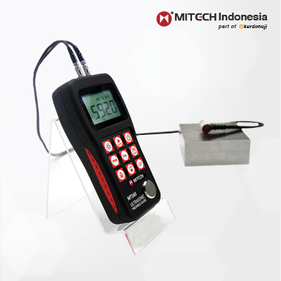
Ultrasonic Thickness Gauge
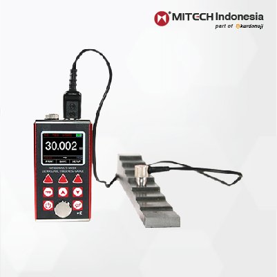
Multi-Mode Ultrasonic Thickness Gauge
References & Cited Standards
- U.S. Department of Energy. (N.D.). Guidance Document for Integrating Quality Assurance During the Design and Construction Life Cycle. Office of Environmental Management. Retrieved from https://www.energy.gov/sites/prod/files/em/QAinDesignGuidance.pdf
- Construction Industry Institute (CII) Quality Performance Measurement Task Force. (N.D.). Quality Performance Measurements of the EPC Process: The Blueprint. Construction Industry Institute. Retrieved from https://www.construction-institute.org/quality-performance-measurements-of-the-epc-process-the-blueprint
- International Organization for Standardization. (2017). ISO 16809:2017 – Non-destructive testing — Ultrasonic thickness measurement. ISO/TC 135/SC 3. Retrieved from https://www.iso.org/standard/72430.html
- Technical data on ultrasonic gauge operation, sound velocity (5920 m/s for steel), accuracy (±0.1mm), measurement range (0.08-635mm), and error sources (surface roughness >6.3μm) synthesized from manufacturer technical specifications (Evident Scientific/Olympus, Cygnus Instruments) and industry training materials from the American Society for Nondestructive Testing (ASNT).
